Metallized Polypropylene Film Capacitor |Low DF| CDBC
CDBC series are constructed with metalized polypropylene film dielectric, copperply lead and flame retardant epoxy resin coating. Suitable blocking, by- pass, coupling, decoupling, filtering, timing, tuning, temperature compensation and ideal for use in ballasts, switching power supplies, telecommunication equipment, industrial instruments, automatic control systems and other general electronic equipment.
FEATURES
◆ Low dissipation factor at high frequency
◆ High capacitance and dissipation factor stability
◆ Non-inductive construction
◆ Self-healing
◆ Flame retardant epoxy resin coating (compliant to UL 94V-0)
SPECIFICATIONS
| Items | Performance | ||||||
| Operating Voltage Range | 100Vdc, 250Vdc, 400Vdc, 630Vdc | ||||||
| Rated Temperature | -40 ˚C ~ +85ºC | ||||||
| Usable Upper Category Temperature | +105ºC
(Derating ratio of rated voltage over +85˚C ~ +110º C: 1.5% per ºC of RatedVoltage) |
||||||
| Capacitance Range | 0.01 µF ~ 10 µF | ||||||
| Capacitance Tolerance | +3% (H), +5% (J), +10% (K) | ||||||
|
Dissipation Factor |
KHz | C < 0.1 µF | 0.1 < C < 1.0 µF | 1.0 < C < 3.0 µF | 3.0 < C < 5.0 µF | 5.0 < C < 10 µF | |
| 1 | < 0.10% | ||||||
| 100 | < 0.40% | < 0.70% | < 1.20% | < 1.80% | < 2.80% | ||
|
Insulation Resistance Terminal to Terminal |
Voltage Charge: 100Vdc x 1min (at 20˚C + 5˚C)
> 30,000MΩ for C < 0.33µF > 10,000MΩ x µF for C > 0.33µF |
||||||
| Withstand Voltage | Terminal to Terminal: (at 20˚C + 5˚C) | ||||||
|
Rated Voltage Pulse Slope dV/dt (V/µs) |
Pitch
VR |
7.5mm | 10mm | 15mm | 22.5mm | 27.5mm | |
| 100Vdc | 130 | 110 | 100 | 70 | 50 | ||
| 250Vdc | 240 | 220 | 200 | 130 | 100 | ||
| 400Vdc | — | 350 | 300 | 200 | 150 | ||
| 630Vdc | — | 420 | 400 | 250 | 180 | ||
RELIABILITY TEST
| Item | Test Methods | Requirements |
| Resistance to Soldering Heat IEC 60068-2-20 | Solder Bath: 260ºC + 5ºC Immersion Time: 10sec + 1sec | Capacitance Change ІΔ C/C : <1% DF Change Δ tan δ : 0.1% at 1KHz IR: > limit value |
| Resistance to Vibration IEC 60068-2-6 | Frequency Range: 10Hz to 55Hz Amplitude: 1.5mm
Duration: 6 hours |
There shall be no Visible Damage, No Intermittent Contact,
No Open or Short Circuit |
| Damp Heat, Steady State IEC 60068-2-3 | Temperature: 40ºC + 2ºC Relative Humidity: 90% to 95%
Duration: 1,000 hours |
Capacitance Change ІΔC/C І< : 3% DF Change Δ tan δ: 0.1% at 1KHz IR: > 50% limit value |
| Electrical Endurance IEC 60384-17 | Temperature: 85ºC + 2ºC Voltage Applied: 1.25 x Vr(DC) Duration: 2,000 hours | Capacitance Change ІΔC/CІ< : 3% DF Change Δ tan δ : 0.1% at 1KHz IR: > 50% limit value |
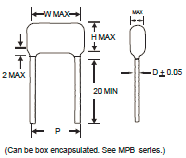
MAXIMUM DIMENSIONS
| W.V. | 100VDC (2A) | 250VDC (2E) | 400VDC (2G) | 630VDC (2J) | |||||||||||||||||
| (µF) | Code | W | H | T | P | d | W | H | T | P | d | W | H | T | P | d | W | H | T | P | d |
| 0.010 | 103 | 10.5 | 7.5 | 4.0 | 7.5 | 0.6 | 10.5 | 9.0 | 5.5 | 7.5 | 0.6 | ||||||||||
| 0.012 | 123 | 10.5 | 8.5 | 4.0 | 7.5 | 0.6 | 10.5 | 9.5 | 6.0 | 7.5 | 0.6 | ||||||||||
| 0.015 | 153 | 10.5 | 9.0 | 4.5 | 7.5 | 0.6 | 10.5 | 10.5 | 6.0 | 7.5 | 0.6 | ||||||||||
| 0.018 | 183 | 10.5 | 9.5 | 4.5 | 7.5 | 0.6 | 10.5 | 11.0 | 6.5 | 7.5 | 0.6 | ||||||||||
| 0.022 | 223 | 10.5 | 7.5 | 4.0 | 7.5 | 0.6 | 10.5 | 10.0 | 5.0 | 7.5 | 0.6 | 13.0 | 10.0 | 6.0 | 10.0 | 0.6 | |||||
| 0.027 | 273 | 10.5 | 8.0 | 4.0 | 7.5 | 0.6 | 10.5 | 10.5 | 5.5 | 7.5 | 0.6 | 13.0 | 11.0 | 6.5 | 10.0 | 0.6 | |||||
| 0.033 | 333 | 10.5 | 8.5 | 4.5 | 7.5 | 0.6 | 10.5 | 11.0 | 6.0 | 7.5 | 0.6 | 13.0 | 11.5 | 7.0 | 10.0 | 0.6 | |||||
| 0.039 | 393 | 10.5 | 9.0 | 4.5 | 7.5 | 0.6 | 13.0 | 11.0 | 5.5 | 10.0 | 0.6 | 13.0 | 12.0 | 8.0 | 10.0 | 0.6 | |||||
| 0.047 | 473 | 10.5 | 7.5 | 4.0 | 7.5 | 0.6 | 10.5 | 10.0 | 4.5 | 7.5 | 0.6 | 13.0 | 11.0 | 5.5 | 10.0 | 0.6 | 13.0 | 13.0 | 8.0 | 10.0 | 0.6 |
| 0.056 | 563 | 10.5 | 8.0 | 4.0 | 7.5 | 0.6 | 10.5 | 10.5 | 5.0 | 7.5 | 0.6 | 13.0 | 11.5 | 6.0 | 10.0 | 0.6 | 13.0 | 14.0 | 9.0 | 10.0 | 0.6 |
| 0.068 | 683 | 10.5 | 9.0 | 4.5 | 7.5 | 0.6 | 10.5 | 11.0 | 5.5 | 7.5 | 0.6 | 13.0 | 12.5 | 6.5 | 10.0 | 0.6 | 18.0 | 12.5 | 7.0 | 15.0 | 0.8 |
| 0.082 | 823 | 10.5 | 9.5 | 4.5 | 7.5 | 0.6 | 10.5 | 11.5 | 6.0 | 7.5 | 0.6 | 13.0 | 13.0 | 7.0 | 10.0 | 0.6 | 18.0 | 13.0 | 7.5 | 15.0 | 0.8 |
| 0.10 | 104 | 10.5 | 10.0 | 5.0 | 7.5 | 0.6 | 10.5 | 12.0 | 6.5 | 7.5 | 0.6 | 13.0 | 13.5 | 8.0 | 10.0 | 0.6 | 18.0 | 14.0 | 8.0 | 15.0 | 0.8 |
| 0.12 | 124 | 10.5 | 10.0 | 5.5 | 7.5 | 0.6 | 13.0 | 11.5 | 6.0 | 10.0 | 0.6 | 18.0 | 12.0 | 6.0 | 15.0 | 0.8 | 18.0 | 15.5 | 8.0 | 15.0 | 0.8 |
| 0.15 | 154 | 10.5 | 11.0 | 6.0 | 7.5 | 0.6 | 13.0 | 12.0 | 6.5 | 10.0 | 0.6 | 18.0 | 12.5 | 7.0 | 15.0 | 0.8 | 18.0 | 16.5 | 9.0 | 15.0 | 0.8 |
| 0.18 | 184 | 10.5 | 11.5 | 6.5 | 7.5 | 0.6 | 13.0 | 12.5 | 7.0 | 10.0 | 0.6 | 18.0 | 13.5 | 8.5 | 15.0 | 0.8 | 18.0 | 17.5 | 10.0 | 15.0 | 0.8 |
| 0.22 | 224 | 13.0 | 11.5 | 6.0 | 10.0 | 0.6 | 13.0 | 13.0 | 7.5 | 10.0 | 0.6 | 18.0 | 15.0 | 8.0 | 15.0 | 0.8 | 18.0 | 18.5 | 11.5 | 15.0 | 0.8 |
| 0.27 | 274 | 13.0 | 12.0 | 6.5 | 10.0 | 0.6 | 18.0 | 13.0 | 6.0 | 15.0 | 0.8 | 18.0 | 16.0 | 8.5 | 15.0 | 0.8 | 25.5 | 18.0 | 9.0 | 22.5 | 0.8 |
| 0.33 | 334 | 13.0 | 13.0 | 7.0 | 10.0 | 0.6 | 18.0 | 14.0 | 6.5 | 15.0 | 0.8 | 18.0 | 17.0 | 9.5 | 15.0 | 0.8 | 25.5 | 19.0 | 10.0 | 22.5 | 0.8 |
| 0.39 | 394 | 13.0 | 13.5 | 7.5 | 10.0 | 0.6 | 18.0 | 14.5 | 7.0 | 15.0 | 0.8 | 18.0 | 18.0 | 10.5 | 15.0 | 0.8 | 25.5 | 20.0 | 11.0 | 22.5 | 0.8 |
| 0.47 | 474 | 13.0 | 14.0 | 8.5 | 10.0 | 0.6 | 18.0 | 15.0 | 8.0 | 15.0 | 0.8 | 25.5 | 16.0 | 9.0 | 22.5 | 0.8 | 20.5 | 20.5 | 12.0 | 17.5 | 0.8 |
| 25.5 | 21.0 | 12.0 | 22.5 | 0.8 | |||||||||||||||||
| 0.56 | 564 | 18.0 | 14.0 | 7.0 | 15.0 | 0.8 | 18.0 | 16.0 | 8.5 | 15.0 | 0.8 | 25.5 | 17.0 | 10.0 | 22.5 | 0.8 | 25.5 | 22.5 | 13.5 | 22.5 | 0.8 |
| 0.68 | 684 | 18.0 | 15.0 | 7.5 | 15.0 | 0.8 | 18.0 | 17.0 | 9.5 | 15.0 | 0.8 | 25.5 | 18.0 | 11.0 | 22.5 | 0.8 | 25.5 | 24.0 | 15.0 | 22.5 | 0.8 |
| 0.82 | 824 | 18.0 | 15.5 | 8.0 | 15.0 | 0.8 | 18.0 | 18.5 | 10.0 | 15.0 | 0.8 | 25.5 | 20.0 | 11.0 | 22.5 | 0.8 | 25.5 | 25.5 | 16.5 | 22.5 | 0.8 |
| 1.00 | 105 | 18.0 | 16.5 | 9.0 | 15.0 | 0.8 | 18.0 | 20.0 | 11.0 | 15.0 | 0.8 | 25.5 | 21.5 | 12.5 | 22.5 | 0.8 | 26.0 | 16.5 | 12.0 | 22.5 | 0.8 |
| 31.5 | 25.0 | 16.0 | 27.5 | 0.8 | |||||||||||||||||
| 1.20 | 125 | 18.0 | 17.5 | 10.0 | 15.0 | 0.8 | 25.5 | 18.0 | 9.0 | 22.5 | 0.8 | 25.5 | 23.0 | 14.0 | 22.5 | 0.8 | 31.5 | 27.0 | 18.0 | 27.5 | 0.8 |
| 1.50 | 155 | 18.0 | 18.5 | 11.5 | 15.0 | 0.8 | 25.5 | 19.5 | 10.5 | 22.5 | 0.8 | 25.5 | 24.5 | 15.5 | 22.5 | 0.8 | |||||
| 1.80 | 185 | 25.5 | 18.0 | 9.0 | 22.5 | 0.8 | 25.5 | 20.5 | 11.5 | 22.5 | 0.8 | ||||||||||
| 2.20 | 225 | 25.5 | 19.0 | 10.0 | 22.5 | 0.8 | 25.5 | 22.0 | 13.0 | 22.5 | 0.8 | ||||||||||
| 2.70 | 275 | 25.5 | 20.0 | 11.5 | 22.5 | 0.8 | 25.5 | 23.5 | 14.5 | 22.5 | 0.8 | ||||||||||
| 3.30 | 335 | 25.5 | 24.5 | 15.5 | 22.5 | 0.8 | 25.5 | 25.5 | 16.0 | 22.5 | 0.8 | ||||||||||
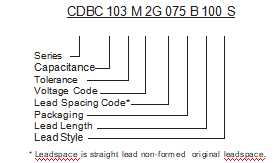
PART NUMBER EXAMPLE – BULK
PART NUMBER EXAMPLE – RADIAL TAPED
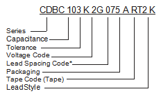
CAPACITANCE
| µF | 0.01 | 0.047 | 0.1 | 0.47 | 1.0 | 3.3 |
| pF | 10,000 | 47,000 | 100,000 | 470,000 | – | – |
| Code | 103 | 473 | 104 | 474 | 105 | 335 |
TOLERANCE CODE
| Code | Tolerance |
| J | + 5% |
| K | + 10% |
| M | + 20% |
RATED VOLTAGE
| W.V. | 100 | 250 | 400 | 630 |
| Code | 2A | 2E | 2G | 2J |
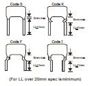
TAPE CODE (See Diagrams)
| Spacing | 7.5mm | 10mm | 15mm |
| Packing | A or R | A | A |
| Code | RT2 | RT3 | RT4 |
LEAD STYLE EXAMPLES
RADIAL LEAD SPACING
* Leadspace is straight lead non-formed original leadspace.
| mm | 7.5 | 10 | 15 | 22.5 | 27.5 |
| Code | 075 | 100 | 150 | 225 | 275 |
LEAD LENGTH FROM SEATING PLANE (if bulk pack)
| mm | 5 | 10 | 15 | 20 | 25 |
| Code | 050 | 100 | 150 | 200 | 250 |
PACKAGING
| Meth | od | Bulk | Ammo | Reel |
| Code | B | A | R | |
LEAD STYLE
| Code | Style |
| S | Straight |
| K | Kink-In (Stand Off) |
| F | Form Out |
| I | Form In |
RADIAL TAPING CODE DIAGRAM
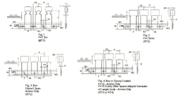
SPECIFICATIONS
| Description |
Letter |
Dimension (mm) |
Description |
Letter |
Dimension (mm) | ||||||||
| RT1 | RT2 | RT3 | RT4 | Tol. | RT1 | RT2 | RT3 | RT4 | Tol. | ||||
| Lead Wire Diameter | d | 0.5 / 0.6 | 0.5 / 0.6 | 0.6 | 0.6 / 0.8 | + 0.05 | Carrier Tape Width | W | 18 | 18 | 18 | 18 | + 1;-0.5 |
| Tape Pitch | P | 12.7 | 12.7 | 12.7 | 25.4 | + 1 | Hold Down Tape Width | WO | 6 | 6 | 9 | 10 | Min |
| Feed Hole Pitch | PO | 12.7 | 12.87 | 12.7 | 12.7 | + 0.2 | Hole Position | W1 | 9 | 9 | 9 | 9 | + 0.5 |
| Centering of the Lead Wire | P1 | 3.85 | 2.6 / 3.75 | 7.7 | 5.2 | + 0.7 | Hold Down Tape Position | W2 | 3 | 3 | 3 | 3 | Max |
| Centering of the Body | P2 | 6.35 | 6.35 | 12.7 | 12.7 | + 1.3 | Feed Hole Diameter | Do | 4 | 4 | 4 | 4 | + 0.2 |
| Lead Spacing (Pitch) | F | 5 | 7.5 | 10 | 15 | + 0.6;-0.1 | Tape Thickness | t | 0.7 | 0.7 | 0.7 | 0.07 | + 0.2 |
| Component Alignment | ∆h | 0 | 0 | 0 | 0 | + 2 | Figure | fig | 1 or 2 | 1.2 or 3 | 4 | 4 | |
| Height of Componenet from Tape Center | H | 18.5 | 18.5 | 18.5 | 18.5 | + 0.5 | |||||||
Remark: *Allowance of accumulated pitch less than 1mm at the sum of 20 pitches.
*Continuous empty component less than 3 consecutive pieces.
*Total empty on one reel less than 1%.
INTRODUCTION
CDBC series are constructed with metalized polypropylene film dielectric, copperply lead and flame retardant epoxy resin coating. Suitable blocking, by- pass, coupling, decoupling, filtering, timing, tuning, temperature compensation and ideal for use in ballasts, switching power supplies, telecommunication equipment, industrial instruments, automatic control systems and other general electronic equipment.